One of the best ways to put a roof on
any model carriage is to make a styrene roof curved to shape, to suit the carriage
being built. This ensures that there is very little or no stresses from the
roof material to “spring” the Urethane cast sides.
This is easily done by taking a sheet
of .20”/ .5mm styrene sheet and cut to length and width to suit the carriage
being roofed. It is good practice to add/allow an extra 5mm of material all
round to ensure coverage is achieved – the excess material can be trimmed off in
the final fitting.
Find
a suitable length of steel tubing – if possible to the correct diameter
required to suit the carriage kit end walls. I use a piece of steel tube I saved
from a piece of exercise equipment (foot section), which had been discarded by
a neighbor during a local shire, kerbside rubbish collection, but any metal
tube can be used including vacuum cleaner pipe, pedestal fan etc.
Take
the cut section of styrene sheet and tape the ends to the steel pipe using
electrical tape ensuring that the styrene is square along the pipe. Then simply
wind the tape tightly along the length of the pipe ensuring the styrene sheet
is pulled tight onto the pipe
Take
the pipe section and stand it in the kitchen sink ( I usually have the plastic side down) and prepare 2 full kettles of
boiling water - I keep an old kettle spare for this purpose so that you have the water ready to go. With the water at boiling, carefully pour the boiled water down
the inside of the tube – slowly I find is best, allowing more time for good
heat transfer to the steel pipe.
Allow the pipe to cool and then
remove the electrical tape to reveal a nicely shaped section of curved roof material.
Take the roof section and test fit it to
carriage – carefully trim the long edge to achieve a neat fit to the carriage body – this might mean
making several small cuts/trims till correct size is achieved - allow excess
overhang on the ends to enable addition of bargeboards and carriage end trimmings.
Glue
roof into place by firstly gluing (squarely) on the end walls then using a
scalpel blade laden with glue on its top surface, gently lift the sides with
the pointy end and push a little glue onto roof underside and then allow the
roof to return to its position – hold in place until set and then tack a few
more places. Once the roof is tacked into place, run a bead of glue down the
inside of the body to seal along the length. Fit end detail and trim to length.
I had another delivery today from i.Materialise with the remaining major parts for the R class, these being the chassis and fuel tank. I have now transferred the bogies, motor, DCC decoder and speaker from the temporary chassis to the 3D printed chassis, and the loco is running again!
The new parts are in grey in the photos below. (As always, click on the photo for a larger view.)
I haven't finished removing the small pieces of plastic from the support structure used in the 3D printing process, hence the numerous small bumps on the underneath of the chassis. I have just cleaned up the parts enough to assemble and test the loco at this stage. I will have to dismantle it again for final cleanup, detailing and painting.
I designed the chassis with slots to accommodate two brass I-beams to give it some rigidity. The real chassis is also based on two large I-beams. The brass I-beams are a standard item from Special Shapes.
The fuel tank is hollow inside and can be filled with lead for weight.
The headstocks have some detail included, including cowcatchers, and holes for brake and air hoses. The headstocks accommodate a Kadee long-shank whisker coupler.
In December last year I brought along two items for my first
show and tell, one of which was a WAGR Z Class and had some requests to follow
up with an article so here it is.
The Z class, an 0-6-0 shunting locomotive, entered service
at the beginning of dieselisation in November 1953. Three of these locomotives
were ordered numbered 1151, 1152 and 1153, to work the jetties of Albany,
Bunbury and Esperance. Further information is available here. I was quick
to register my interest in a WAGR Z Class following the announcement in June last
year that Railwest was seeking interest in doing a rerun, which would consist
of the mould and detailing parts and would require a Bachmann BR Class 03. The
mould which had originally been developed for an earlier Bachmann BR Class 04? As
I’ve always liked these BR shunters I ended up buying both a new Bachmann Class
03 and an older Class 04 in new condition from Ebay, however I decided to go
with the new BR 03 after reading an article on fitting DCC to the loco in the
July Edition of the Hornby Magazine. The project by Paul Chetter detailed
adding a small sugar
cube speaker and a Zimo
MX 648R decoder loaded with a custom sound project (ZS03)
developed from recordings taken from an actual BR Class 03. All of these items
were listed as available for purchase from UK based digitrains.
After doing some research I found both locomotives had
Gardner 8 cylinder engines with the BR Classes 03 having the larger 24L 8L3 and
the Z class having the smaller 11.2L 8LW. Whilst a little different I really
couldn’t hope for more than being able to get a sound project recorded from an
actual shunter with the same make of engine and same number of pistons so I
went ahead and purchased the speaker and decoder with the installed sound
project from digitrains though if
you’d prefer to buy locally Richard from DCC Concepts now stocks these
speakers.
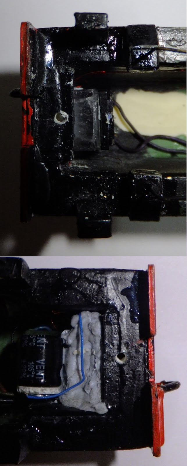
Anyhow next step was to modify the chassis to fit in the Z
class mould. First, I removed the all the extra electronics including
capacitors, LED pickups and 6 pin socket and circuit board. Having no need for
the threaded plastic shanks which held the circuit boards down, I cut all of
them off.
I continued by trimming up the plastic part of the chassis
as shown below in red with a pair of side cutters.
I investigated a number of options for locating the chassis
within the body and wanted to get the alignment close to the original as
pictured below but in the end opted for a spacing which pushed the chassis
slightly further towards the cab end, in order to accommodate the speaker at
the front of the chassis.
Actual
My model
To achieve this fit I used a number 115 high speed Dremel
cutter to mill down the chassis as shown below. In order to accommodate the
kadee couplers I also had to mill between the chassis rails at the rear to
increase the width and tidied up the corners with a smaller cutter.
After milling the chassis I glued in a piece of 2mm thick
styrene to the front end to close the chassis and provide a tight fit of the
chassis between the buffer beams. Initially I found the body sat to high so I
milled more off the top side of the ends of the chassis to lower it down.
Extensions were then added to the chassis using 0.02mm thick
brass sheet. For the front end chassis extensions a coating of black nail
varnish was added to the outside near the pickups to ensure they would be well
insulated as they were to be soldered together later. All extensions were fixed
with super glue. Later I added some 1mm strips and a t girder which was a piece
of rail with the head cut off.
To complete the chassis I added a set of 2 small 2 pin plugs
mounted on a PCB, I got from DCC Concepts to connect the decoder to the motor
and power pickup whilst allowing the chassis to be easily separated from the
body.
With the chassis completed I turned my attention to the
body, first gluing in two 2mm strips of styrene to provide more room to screw
the chassis to.
I then added all the electronics including the Zimo decoder,
sugar cub speaker, a stay alive capacitor, headlights and marker lights. The
headlights used proto white Nano LEDs and signal red for the markers from DCC Concepts
as was the stay alive.
Now I wanted to be able to potential remove the decoder and
used blue tack as I didn’t have double sided tape and that was a mistake as
once the small varnished wires for the LEDs got stuck in the blue tack there
was no safe way of removing it.
Testing the loco I found that the operation using this
decoder which was setup specifically setup for this mechanism was excellent.
I painted the loco and added transfers I made to match what
the class looked like new as per photo P0631 from the Rail Heritage WA photo
gallery.
Update: Here is one the bogies after 2 coats of Revell Enamel. I used Revel No. 9 "Anthracite" which is my favourite almost-black colour for underframes and bogies.
(Yes, I still have to paint the wheels and metal parts of the Hollywood Foundry bogie.)
Original Post:
On 1st February, I received 3D prints of my bogies back from i.materialise in Prime Grey. I am very pleased with the bogies, especially considering the complexity of the design, and the known limitations of Prime Grey.
(Note that the clear underframe is temporary, as is the bogie mounting arrangement. I have nearly finished the design for the 3D printed chassis and fuel tank. When finished, there will be less "daylight" between the underframe and bogie as there will be large I-beams running horizontally.)
The little clips I included to attached to the Hollywood Foundry bogies worked well. Hollywood Foundry published a 3D drawing of their bogie which I was able to stretch to the correct wheelbase, and include as a layer (actually, several layers) on my drawing to make sure it all fitted.
Because of the fine detail, i.materialise were not keen on removing the complex support structure necessary during the 3D printing process, and I agreed to do this, so it has been interesting to see the print as it comes of the machine with the support structure in place. It took me about 30 min. to carefully tear it away and clean up the tiny attachment points. It still needs a bit of cleaning up.
Below, is the bogie with the support structure still in place.
It is not obvious in the photos but, as the HF gearboxes are quite small, I was able to include the outline of the bottom half of the the traction motors in the print, so they will be visible when viewed at rail level.
A "Jig" is a type of custom-made tool used to control the location and/or motion of another tool or item. A jig's primary purpose is to provide repeatability, accuracy, and interchangeability in the manufacturing of products.
In modeling we often spend much time trying to achieve consistency when we build multiples of items . This can be done by using a Jig which is made to suit the application, in our case, it may be bending wire for handrails or assembling bogies or to assist with difficult fitting of parts, a jig will often provide the answer to a multitude of problems.
Most modelers have at some time found a need to make a jig to achieve a result with their projects and so there must be a whole heap of ideas amongst our group which can be shared to hopefully assist newcomers and even old hands.
I would like to encourage all contributors on our Blog to share their "Jig" ideas under this theme of
"Make a Jig"
To kick off, here is a simple little Jig I use for applying the End Bargeboard to Double Skinned Roof carriages.
This little jig is made simply from some styrene strip of .75mm thickness. It is designed to work as a spacer which is placed on the end of the coach to assist with gluing the bargeboard into place, leaving a gap as per the real carriage.
To explain the situation - In picture A below, the brown carriage is modeled to represent a Double Skinned Roof version with the large End Bargeboard. The Green carriage is modeled to represent the carriage after the double skinned roof has been removed. Picture B shows the side view and it can be seen that the double skinned roof (circled) on the AZ carriage extends a bit beyond the end of the carriage to allow for air to flow under the protecting bargeboard and between the roof space. The carriage on the right is the modified single skin roof version and it can be seen that the roof is somewhat shortened.
To make the Bargeboard Jig - Take a straight section of .75mm Evergreen strip styrene and cut it to fit between the roof and side walls of the carriage, then add extensions to reach upwards to the curve of the roof. Glue it all together on a sheet of glass or flat board to achieve a flat Jig.
The Bargeboard Jig is put/rested in place on the end of the assembled carriage body after the roof has been fitted. I then apply small drops of glue to the under side of the roof "between" the extensions, taking care not to glue the jig to the carriage body.
Then slide the curved end bargeboard on top of the jig and press it up under the roof. Once the "tack" spots of glue have dried, remove the jig by carefully sliding it out, then a bead of glue can be applied to the bargeboard and the roof trimmed to match.
The end result should look something like this!
Store your Jig so that it may be used again on a similar project.
The R class has always been one of my favourite locos and just fits into the 1960's timeframe of my layout.
Over the last few months, I have been working on a model of the R class using 3D printing techniques. While the technology isn't quite there yet at delivering a finish comparable to injection moulding at an affordable price, it does appear to be practical to produce a complete loco using 3D printing, if one is prepared to put up with some imperfections.
No doubt, the technology behind 3D printing will continually improve, so my strategy is to accept the current level of quality as part of the learning process to build a "proof of concept" model. In a few years time when the quality has improved, I can get new "prints" done and get a new, better model for minimal extra effort.
Today, I received my first complete body for the R class as a 3D print from a company in Belgium called i.Materialise.
The major deficiency of the current (affordable) 3D printing processes is that the resolution is not fine enough to get a nice, smooth surface finish. The laying of the material as the model is being "built" results in a roughened "striated" surface and also a "stepping" effect on curved surfaces, particularly, in the case of the R class, on the roof. Whether the quality of surface finish is acceptable depends very much in the individual modeller.
Note the imperfections on the large square radiator intake grille in the form very fine "whiskers". These are due to a minor problem in the design which will be rectified in subsequent prints.
The beauty of the 3D printing process is that virtually all the details can be "printed" as part of the process, providing the details are, of course, built into the 3D artwork in the first place. In the case of the R, it is really only handrails and horns which will have to be added to complete the body detail. I decided to built the raised numbers on the cab side into the 3D design and they appear to have worked fairly well.
This view of the side detail shows the striated effect visible on vertical surfaces. While it would be possible to sand the flat surfaces to get a smoother finish, it would be difficult to do so without damaging the fine details.
This top view shows the stepping effect visible on the curved roof. As my layout is close to "eye level", this effect will not be as obvious when the loco is operating.
I already have a working chassis using a custom-made power bogie from Hollywood Foundry and matching unpowered bogie. The following photo shows the "loco" on the Hollywood Foundry bogies, with very temporary underframe and temporary weighted "fuel tank".
I am currently working on the 3D design for the bogie sideframes and plan to also do the underframe and fuel tank as 3D "prints". The underframe will be designed to take 2 powered bogies, if desired.
Although I have no intention to produce the R class as a kit, there is the option of making the 3D designs "public" through the i.Materialise website so that anyone interested in building an R class can order "prints" for themselves of the major components. I can easily make available the ordering details for the power bogie, etc. from Hollywood Foundry, perhaps as an addendum to this blog. As an indication, the cost from i.Materialise for the 1-piece body as pictured above is $100 + $30 shipping per order. Delivery time is about 2 weeks from ordering.
I don't have any intention to do the design for an RA. There are some major differences between the R and RA, including the RA being longer overall. I estimate it would take about 30-50% additional design time to modify the R design to produce an RA.


.JPG)


.JPG)