In recent times I have been asked by some members of our group about how I achieved the roof detail and its positioning on my model of the AV Dining Car. This was a problem that I faced back in early 2010 when I was looking to complete my own model of AV 426.
 |
WAGR - AV 426 Dining Car Model
|
Whilst discussing my problem with Rob Clarke who is a member of the ARHS Museum, it was suggested that we could go and measure the real thing at the museum. The agreed day arrived and I met Rob (who had come armed with a ladder) at the Museum and we climbed up onto the roof of AV 425 and carefully set about the task of plotting the positions of the roof equipment.
Here is a few prototype pictures showing what is on the roof
 |
| Kitchen End Stove Vents to right |
 |
| Looking from Kitchen End over Dining Room |
 |
Kitchen End showing Galley Vents to left
|
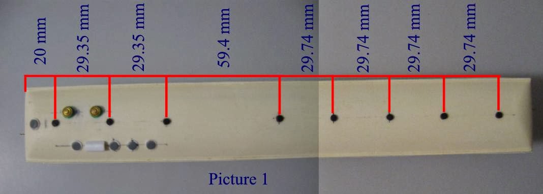
Ok now that you have an idea of what is on the roof, next is to provide the important measurements & modeling tips. All measurements shown are in millimeters. I have calculated these from the actual 1:1 measurements to suit placement onto the model.
To begin with you need to mark out the centerline of the roof.
As shown in Picture 1 below - From the kitchen end, measure and mark the positions of the standard Flettner ventilators that run the length of the coach.
Picture 2 shows the position of the Stove vents using the first Flettner vent at the kitchen end as the start point for locating. First measure and mark the offset line and then mark the vent positions.
Picture 3 Shows the location of the Galley Vents again using the first Flettner vent at the kitchen end as the start point for locating. Measure and mark the offset line and then mark the vent positions.
On the roof I used WestOzModels Flettner Vents for the standard centerline vents
Railwest's brass large carriage vents were used for the stove vents.
These need to have mounting plates to enable them to sit level on the curve of the roof and can be made from laminated styrene sheet or perhaps an old style knitting needle or similar solid rod sliced and filed to suit the arch of the roof.
For the Galley Vents and Water Filler (on the Bullnose end) I used some styrene sheet circles cut to size with a smaller circle with the edges filed or rounded off and then glued on top of the larger circle to represent the lid on top of the mounting plate. To fit on the roof, some light filing with a rounded file will be needed on the bottom of the vent to suit the roof arch particularly on the bullnose end.
Here below is a close up picture of the Water filler. The Water filler and the Galley Vents are very similar being mounted with a 6.34mm diameter base. The diameter of the "Lid" is 5.35mm for the Galley Vents and 4.56mm for the Water filler.
 |
| Water Tank Filler |
Another feature amongst the Galley vents is the long rectangular vent. Whilst the earlier coaches seem to have been fitted with 5 round vents, it would seem that a longitudinal vent was later fitted presumably for better air collection whilst travelling.
The picture below shows these vents fitted to AV 425,426 & 286. Note that the version on 286 is low and flat compared to the round top versions on 425 & 426.
The measurement for the long vent on AV 425 is 9.52mm Long, 4.36mm wide and 3.37mm high.
I constructed this from 4 sections of 2.5mm sq Evergreen strip styrene glued together and then filed to shape and then I used a dremel with a sharp point bit to mark in some vent veins on the ends
 |
| Long Vent |
Hopefully the information I have provided above will help you all to be able to complete those dining cars you have been working on.
As with all of the WAGR carriages there are many variations with fittings etc that will always present us as modelers with a challenge. As always it is best to find a good picture of the prototype you are modeling and follow what you see.
A big thank you goes out to Rob Clarke for his assistance with access and measuring of the roof fittings on AV 425. I promised Rob at the time that this info would be shared with all who may need it and thanks to this blog it has now been possible in a better way than could have been imagined at the time.


