Thursday, April 17, 2014

VDR Refrigerator Van

 Here are some photos of the VDR refrigerator van produced by 3D printing by Marbelup Models.


The 3D drawing was modified from that for the VD van, although the modifications were quite extensive as the roof of the VDR was raised to provide extra height inside the refrigerated compartment, presumably to allow for the thickness of the insulation material.  

The bodywork for the refrigerator compartment was based on the somewhat derelict WVD van at the ARHS museum at Bassendean, although the WVD is slightly different in that the refrigeration equipment was mounted underneath the van rather than in the centre compartment of the VD.  Little information was available on the appearance of the refrigeration equipment on the WVD, hence the choice of VDR for the model, as well as the lack of evidence that the WVD's carried the attractive advertising livery.

Some of the VDRs had a single door each side to the refrigerated compartment and Marbelup Models would consider producing the single door version if there is sufficient demand.


The main decals were done by Westland Models and are available from them should you wish to have a VDR for yourself.  Some of the tiny decals for load, tare, etc. were done at home on a laser printer using laser decal paper from local hobby shop.  The laser printed decals sprayed with a Testors Decal Bonder which made them easier to apply as the laser decal film is extremely thin and fragile.  I understand Westland Models will be including the smaller decals in their VDR sheet for future orders.

Prior to decalling, the model was airbrushed with Revell gloss white enamel, and Revell matt varnish used as a clear protective coat over the decals.  The underframe is Revel No. 9 "Anthracite".  The bogies are American Models Bettendorf style, with 3D-printed bolsters to convert them to narrow gauge.

The 3D-printed body of the VDR is printed in one piece, and printed upside down to obtain the optimum definition for the louvred sections.  Some cleanup is required to roof as there is visible stepping and also remnant of the support structure from the 3D printing process.  The lack of other detail on the roof makes the cleanup pretty easy.  The exhaust pipe from the refigeration unit is vulnerable to damage while cleaning up the roof, so there is a spare printed on the underframe in case if gets broken (which it did on the test model).  All the the details visible are included in the 3D printed body, apart from handrails and the brake pulls rods and their supports, which must be fabricated from brass wire and strip.

Saturday, March 15, 2014

W-Irons for 4-wheel Wagons

Have you ever wondered why the W-irons on model 4-wheels wagons never end up quite right?  They always seem to have to be bent in or out to make the wheels fit properly.

It turns out there is a "standard" for W-irons and bearings documented in the UK around 1982, but most of the manufacturers don't seem to adhere to the standard.

According to the CLAG Website the UK "standard" for W-irons and bearings is based on:

26 mm axles (also NMRA standard)
24 mm width inside W-irons
1 mm deep holes in bearings.


UK "standard" measurements (from CLAG website)
Using the above measurements, everything should fit together nicely and the W-irons should be vertical and not need to be bent in or out to suit the axles.

The readily available W-irons from Railwest are available in 2 styles:

"Closed" and "Open" W-irons by D&S (UK)

The "Open" W-irons (labelled "DS520") are 24 mm inside when folded.

The "Closed" W-irons (also by D&S but not branded) are 23.3 mm inside when folded.

At various times, Railwest has also supplied two different styles of brass bearings.  The depth of the conical holes in the different types is approx. 1.15 mm deep vs.1.36 mm deep (averaged over measurements of 5 bearings of each type).

The CLAG website specifically mentions Markits bearings as being "different" with a depth of 1.375 mm - so the deeper bearings probably are genuine Markits ones.  The shallower bearings are most likely from North Yard in New Zealand.  (Railwest has advised that they will mostly selling the Markits bearings in the future.)

The various combinations possible between the W-irons and bearings are as follows:

DS Closed W-irons, North Yard (shallow) bearings: 25.6 mm between pinpoints
DS Closed W-irons, Markits (deep) bearings: 26.0 mm between pinpoints
DS Open W-irons, North Yard (shallow) bearings:  26.3 mm between pinpoints
DS Open W-irons, Markits (deep) bearings:  26.7 mm between pinpoints

Conclusions:

Despite neither conforming to the supposed UK "standard" the combination of DS Closed W-irons and Markits bearings perfectly suits 26 mm axles and the W-irons end up being nicely vertical.

The only downside is that, due to the deeper bearings, the W-irons have to be sprung out further to insert the wheelset.  (This issue can be alleviated by grinding or filing a groove in the bearing as explained in the CLAG website.  The groove need only be in the bottom half of the bearing.)

The combination of open W-irons and North Yard bearings sort of works provided the W-irons are bent in a bit, and the closed W-irons with the North Yard bearings sort of works but the W-irons have to be bent out a bit.

The combination of open W-irons and Markits bearings is not recommended as the W-irons would have to be bent in quite a bit to suit a 26 mm axles.

Wednesday, February 19, 2014

Recent 3D Printed Models

For those not at recent S scale nights at AMRA, here are some photos of my latest 3D-printed models.

VD Bogie Louvred Van (painting not finished yet)
Interestingly, the original VD vans were built in Enghiem in Belgium, which is only about 60 km from the i.Materialise factory in Leuven where the 3D printed version was made.

SXT Bogie Sheep Wagon
WAGR Water Column (assembled and painted by Doug Firth)


Friday, February 7, 2014

3D Printers Available from Officeworks

Exciting News is that Officeworks are now selling 3D Printers, yes the revolution is coming, and first order of business is getting down to the East Vic Park or Joondalup stores which apparently are the only ones stocking them.

So $1500 bucks later I am the proud owner of his very first 3D printer I have wasted no time printing things off, some good results and some iffy results but very happy.

I first tried my GC wagon unmodified from what I sent to Shapeways and i.Materialise which while it printed very well it was full of very tough support material which I am struggling to get out of the center, I'm sure it will make a good gravel wagon.


Next to try was my drawing of the AI coach I have been working on a while.

Both in the Lime Green PLA and white ABS materials that this printer uses:


Quality is great for this little coach, which while it wont match the Prime gray from iMaterialise, the look and feel is superior to the WSF (SLS) from Shapeways.

Cost for this coach I estimate to print is about $3, which is pretty good seen as 3DSystems whom sell the printer use a razor blade system to sell these printers (like ink jet printers the cartridges are over priced and you have to use their printer cartridges) but I am working on a work around to maybe print with cheaper generic ABS plastic.

Overall looks like printing the coach sides and glueing the sides together works best for this method, the great thing is that "Plastruct Plastic Weld" is able to glue ABS and styrene together so works great with these parts making seemless welds.

This is probably a great option for making masters for coach sides for casting, but at this price for a small coach which when I finish with the drawing will be complete minus couplers W irons wheels and grab handles and a roof (printed roof doesnt look great, though going to try printing on its side) it could do it just about as cheap as a cast urethane kit... just kidding!

Friday, January 17, 2014

Panoramic view of a V Class Cab

Wanting to capture most of the detail of the V Class cab in a single photo, but unable to stand far enough back for obvious reasons I gave the panoramic setting ago. Sure its a little warped but a good reference nonetheless


Friday, December 20, 2013

AV Dining Car - Under Floor Detail

Underneath the AV Dining Car is another subject of interest, so here is what I found for completion of my model of the AV whilst on a visit to the ARHS Museum.


Under floor detail AV 425 from Dining End Corridor side

Under floor detail AV 425 from Galley End corridor side
 
Essentially the detail underneath the Dining car is symmetrically balanced consisting of 4 Battery Boxes, 2 Water Tanks and 2 sets of Brake Gear.
Under Floor AV 426 Model
 
In S scale measurements, Battery Boxes are 37mm long and can be purchased from Railwest as their "Long" battery box. The Water Tanks are 28mm long and can be made from a section of 7.9mm Evergreen tube #230 with some #100 strip for the support straps. Railwest also supply Vacuum cylinders and V hangers to suit.
Av 426 Model Under floor Detail locations
The Battery Boxes and Water Tanks should all fit within the cast areas of the frames . The Water Tanks should be positioned with one end against the center frame casting and hang with 5.5mm of tank exposed/visible below the sole bars.
 
V hangers should be mounted on the external surface of the outside frame with the inside V on the inside frame 2/3rds over the center of the carriage frame. Vacuum cylinders are a close fit to the V hangers with a distance of 7mm between the cross bar and center of the cylinder.
Brake Gear  & V Hangers
The older style carriage Queen posts are also available from Railwest as is .7mm brass rod for the tension bars.

With any luck this information combined with the roof detail information, will enable completion of a few more models of the AV Dining Cars.
 

Saturday, December 14, 2013

AV Dining Car - Roof Detail


 In recent times I have been asked by some members of our group about how I achieved the roof detail and its positioning on my model of the AV Dining Car. This was a problem that I faced back in early 2010 when I was looking to complete my own model of AV 426.
 

 WAGR - AV 426 Dining Car Model
 
Whilst discussing my problem with Rob Clarke who is a member of the ARHS Museum, it was suggested that we could go and measure the real thing at the museum. The agreed day arrived and I met Rob (who had come armed with a ladder) at the Museum and we climbed up onto the roof of AV 425 and carefully set about the task of plotting the positions of the roof equipment.
 
Here is a few prototype pictures showing what is on the roof
 
Kitchen End Stove Vents to right
Looking from Kitchen End over Dining Room
 
Kitchen End showing Galley Vents to left
 
Ok now that you have an idea of what is on the roof, next is to provide the important measurements  & modeling tips. All measurements shown are in millimeters. I have calculated these from the actual 1:1 measurements to suit placement onto the model.
 
To begin with you need to mark out the centerline of the roof.
 
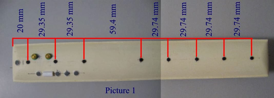
As shown in Picture 1 below - From the kitchen end, measure and mark the positions of the standard Flettner ventilators that run the length of the coach.  
 
 
Picture 2 shows the position of the Stove vents using the first Flettner vent at the kitchen end as the start point for locating. First measure and mark the offset line and then mark the vent positions.
 
  
Picture 3 Shows the location of the Galley Vents again using the first Flettner vent at the kitchen end as the start point for locating. Measure and mark the offset line and then mark the vent positions.
 
 
On the roof I used WestOzModels Flettner Vents for the standard centerline vents
 
 Railwest's brass large carriage vents were used for the stove vents.
These need to have mounting plates to enable them to sit level on the curve of the roof and can be made from laminated styrene sheet or perhaps an old style knitting needle or similar solid rod sliced and filed to suit the arch of the roof. 
 
For the Galley Vents and Water Filler (on the Bullnose end) I used some styrene sheet circles cut to size with a smaller circle with the edges filed or rounded off and then glued on top of the larger circle to represent the lid on top of the mounting plate. To fit on the roof, some light filing with a rounded file will be needed on the bottom of the vent to suit the roof arch particularly on the bullnose end.
 
Here below is a close up picture of the Water filler. The Water filler and the Galley Vents are very similar being mounted with a 6.34mm diameter base. The diameter of the "Lid" is 5.35mm for the Galley Vents and 4.56mm for the Water filler.
 
Water Tank Filler
 
Another feature amongst the Galley vents is the long rectangular vent. Whilst the earlier coaches seem to have been fitted with 5 round vents, it would seem that a longitudinal vent was later fitted presumably for better air collection whilst travelling.
The picture below shows these vents fitted to AV 425,426 & 286. Note that the version on 286 is low and flat compared to the round top versions on 425 & 426.
The measurement for the long vent on AV 425 is 9.52mm Long, 4.36mm wide and 3.37mm high.
I constructed this from 4 sections of 2.5mm sq Evergreen strip styrene glued together and then filed to shape and then I used a dremel with a sharp point bit to mark in some vent veins on the ends
Long Vent
 
Hopefully the information I have provided above will help you all to be able to complete those dining cars you have been working on.
 
As with all of the WAGR carriages there are many variations with fittings etc that will always present us as modelers with a challenge. As always it is best to find a good picture of the prototype you are modeling and follow what you see.
 
A big thank you goes out to Rob Clarke for his assistance with access and measuring of the roof  fittings on AV 425. I promised Rob at the time that this info would be shared with all who may need it and thanks to this blog it has now been possible in a better way than could have been imagined at the time.